Installation Guide for RUGAVAL Expansion Joints
Installation and Operation Hints for RUGAVAL Expansion Joints
Rubber Flexible Joint Malaysia | Single Bellow | Rubber Bellow Supplier in Malaysia
RUGAVAL expansion joints are provided ready for installation. The standard flanges can be turned into any desired posi- tion. Additional sealings usually are not necessary. For instal- lation please observe the following :
-
1) Prior to the installation of the expansion joint ensure that the mating flanges have satisfactory sealing surfaces. Protruding pipe ends, grooves and tongues are not per- mitted as the sealing surface of the bellows might be destroyed.
Attention: When using slip-on flanges the outside diameter must be larger than the sealing surface of the expansion joint.
-
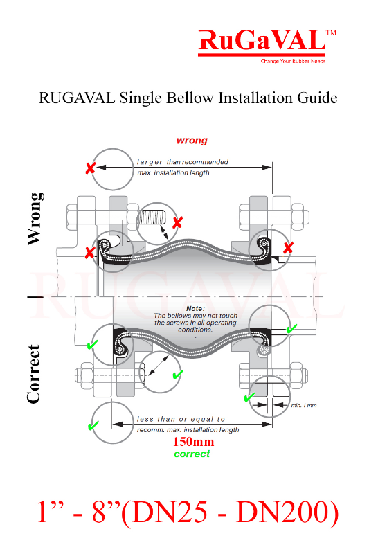
2) Pay attention to the correct installation length: The pulling of expansion joints into installation gaps which are too large will lengthen the rubber bellow and might lead to the collar being drawn out of the flange groove (see picture). During the subsequent tightening of the screws the collar of the bellows would be crushed asymmetrically.
Please note : A considerable lengthening during installation decreases the allowable range of movement during operation. To shorten installation gaps, distance flanges are available.
-
3) If possible install the expansion joints in such way that the date of production is visible.
-
4) Screws should be inserted from the expansion joint side. If this is not feasible, it must be assured that the bellows may not touch the screws in all operating conditions.
-
5) We recommend to use bolts of property class 8.8. The bolts have to be fastened crosswise in 3 uniform steps.
When using a torque wrench:
1st step:
Tighten bolts equally by hand (pay attention to parallel sealing surfaces!).2nd step:
Fasten crosswise with torque 50 Nm. -
3rd step:
Fasten crosswise -
6) If no torque wrench can be used during installation, the screws may only be tightened to an extent that between the metal flanges a distance "y" of at least 1 mm remains (see picture).
7) The test pressure of a bellow or flange is 1.5 x PN. This value depends on which component is weaker.
8) The rubber bellow of the expansion joint must not be painted ! Solvents can damage the rubber cover, further- more the colour coat impedes a proper visual inspection.
9) When welding and cutting, the rubber bellow must be protected against heat by all means. For electric welding it must be insured that the electric current does not pass through the bellows.
10) Permanent radiation heat above 90° C must be avoided. If necessary flame protection covers should be used (see page 471).
11)Rubber expansion joints are subject to wear and must be included to routine inspection of the pipe system (visual inspection of the expansion joint regarding damages as well as inspection for hardening by pushing in with a thumb).
DN 80 DN 300 DN 500 DN 700 DN 800 DN 900 DN 1000
approx. torque max. 80 Nm max. 100 Nm max. 130 Nm
250 Nm 300 Nm 310 Nm 340 Nm
y = min. 1 mm
Do not use any sharp-edged tools which might damage the rubber bellow in case the tool slips.